The Boost Converter
How a step-up converter works, and how you control it.
Welcome
A boost converter raises a DC voltage. You put a low voltage in, and you get a higher voltage out.
A common use is solar charging. The panel sits at 12 V and the battery you want to charge sits at 24 V. Wire them together directly and nothing happens, because the panel cannot push current into a battery that sits above it. Put a boost converter in between, and it lifts the panel's 12 V up to 24 V so the battery charges. That is what this course is about: how the boost does that, and how you control it.
A boost works much like a buck converter, so this course assumes you know how a buck works. If you do not, read the buck guide first. That is the only thing you need from it.
Here is the plan:
- Chapter 1: how a boost differs from a buck, physically.
- Chapter 2: how the boost behaves: its inductor current, its output voltage, and the averaged model.
- Chapter 3: the control objectives and the two controllers you can use.
- Chapter 4: the two controllers in action.
A few things are covered in more depth in the buck guide: sizing the inductor and capacitor, and how the control loops are built and tuned. You do not need any of it to follow this course, but that is where to look if you want the detail.
Alongside the course, try the boost yourself in the boost simulator. Every plot in the course has a link that opens the simulator on that same example.
The converter we'll come back to
We use the same converter all the way through the course: a 12 V panel charging a 24 V battery. It is a two-times step-up. The numbers match the boost simulator, so everything here is something you can reproduce on screen.

| Symbol | Meaning | Value in this guide |
|---|---|---|
| $V_{in}$ | Solar-panel voltage (the lower source) | $12\ \mathrm{V}$ |
| $V_{out}$ | Battery voltage (the higher bus) | $24\ \mathrm{V}$ |
| $D$ | Duty cycle ($=1-V_{in}/V_{out}$) | $0.5$ |
| $I_{out}$ | Battery charging current | $2.4\ \mathrm{A}$ |
| $I_{in}$ | Panel current ($\approx P/V_{in}$) | $\approx 4.8\ \mathrm{A}$ |
| $P$ | Power | $\approx 58\ \mathrm{W}$ |
| $L$ | Inductor | $100\ \mu\mathrm{H}$ |
| $C$ | Output capacitor | $100\ \mu\mathrm{F}$ |
| $R$ | Battery (modelled as a resistor) | $10\ \Omega$ |
| $f_{sw}$ | Switching frequency | $100\ \mathrm{kHz}$ |
Notice the two currents. The panel current is larger than the battery charging current. Power in equals power out, and the panel voltage is the lower one, so the input side has to carry more amps. That is the opposite of the buck, and it matters later.
The boost versus the buck
The boost and the buck use the same parts: two switches, an inductor, and an output capacitor with a load. What changes is where the parts sit.
Why step up at all?
A buck lowers a voltage. You use one when the source is higher than the load needs.
Often the problem is the other way round. A solar panel gives 12 V. A single battery cell gives 3.7 V. The system around it needs more than that: a 24 V or 48 V battery bus, a string of LEDs, or a few hundred volts for mains electronics.
When the load needs a higher voltage than the source gives, you need a boost converter.
The same circuit, input and output swapped
Here are the two converters, drawn at the same scale.

In the buck, the input feeds the top of the half-bridge, and the inductor carries power out to the load.
In the boost, the inductor sits at the input and feeds the switch node. The output is taken from the top rail.
The switches are the same parts doing the same job, pulling the switch node up or down. The circuit has been turned around, and power now flows the other way through it.
A boost is a buck with the input and output swapped. Same two switches, same inductor, same capacitor and load. The inductor has moved to the input side. What you already know about the switches and PWM still applies.
The duty cycle and the voltage ratio
Both converters use the same half-bridge, driven the same way. But they do not name the duty cycle after the same switch.
The buck names it after the top switch. $D$ is the fraction of the cycle that the top switch is closed, and the output is
$$ V_{out} = D\,V_{in}. $$The boost names it after the bottom switch, which is the one it actively drives. With that $D$, the output is
$$ V_{out} = \frac{V_{in}}{1-D}. $$Those two look nothing alike. But that is only the naming. Measure both converters by the same switch and the difference goes away.
Take the top switch in both, and call that fraction $D_{top}$. For the buck it is just $D$. For the boost the two switches are complementary, so $D_{top} = 1-D$. Put that in and you get
$$ \text{buck:}\quad V_{out} = D_{top}\,V_{in}, \qquad\qquad \text{boost:}\quad V_{out} = \frac{V_{in}}{D_{top}}. $$They are reciprocals. With the same gate timing, the buck multiplies the input by the duty and the boost divides by it.
Now swap the input and the output as well, and the two become the same equation. Write the boost relation the other way round:
$$ V_{in} = D_{top}\,V_{out}. $$That is the buck formula with $V_{in}$ and $V_{out}$ exchanged. It has to be. The boost is the buck with its input and output swapped, so the equation is swapped in exactly the same way. The two converters do not obey different laws. They obey one law, read from opposite ends.
The gate timing is the same in both converters. Read it off the top switch, and the buck multiplies the input by that duty while the boost divides by it. Swap the input and the output too, and the two formulas are identical: $V_{in} = D_{top}V_{out}$ is the buck's own equation with the ends exchanged. The $1-D$ you see in the boost formula is only there because a boost names its duty after the bottom switch it drives.

The step-up mechanism
Why does swapping the ends raise the voltage? Follow the inductor through the two states. Which state you are in depends on which switch is closed. The green loops below show where the current goes.


Bottom switch closed (top figure). The inductor sits across the input, so it sees the full $V_{in}$. Its current rises and it stores energy. The output is cut off from the inductor, so the capacitor supplies the load on its own.
Top switch closed (bottom figure). The inductor current keeps flowing, and now it flows out to the output. The inductor voltage adds to the input voltage. The two in series put the output above the input.
So the boost stores energy while the output is disconnected, then releases that energy in series with the input. That is the step-up mechanism.
It also means the output is fed in pulses, only during the second state. That matters when we size the capacitor.
The diode (asynchronous) version
A boost can also be built with a diode instead of the top switch. That version is called asynchronous. The bottom switch is still driven. The top switch becomes a diode that passes current to the load by itself.

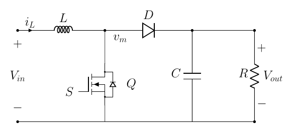
The trade-off is the same as in the buck. A diode is cheaper and needs no gate drive. But it drops a fixed forward voltage, so it wastes more power, and it passes current only one way, so the converter cannot run backwards.
A second switch costs more and has to be driven. In return it conducts with very little loss and lets power flow both ways.
We use the two-switch version for the rest of the course. It is easier to follow, because you drive both switches and always know which one is on.
A boost is a buck turned around. Same parts, input and output swapped. The voltage ratio inverts, from $V_{out}=D\,V_{in}$ to $V_{out}=V_{in}/(1-D)$. You can build it with two switches or with a switch and a diode, just like the buck. The next two chapters cover what is new.
Sign in to continue
Chapter 1 is free. Sign in to read the rest of the course: the inductor current and the output voltage, the averaged model, the wrong-way response, and the two controllers in action.
Sign in to continue